XFT-BT / XY-BT case + battery charging mod (uses 13650 v...
Assembly requirements:
In order to make it, you'll need:
— Microsoldering abilities (the job is quite difficult for a beginner, you'll be soldering a SOT package)
— A XFT-BT/XY-BT board attained from AliExpress or other online retailers.
— A USB C breakout board (with or without a bracket), mine had it (was also sourced from AliExpress)
— Some amount of AWG30 (0.25mm sq) or perhaps smaller gauge wire.
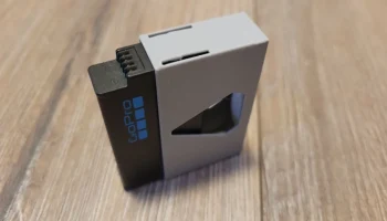
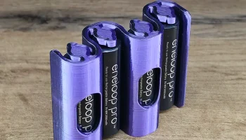
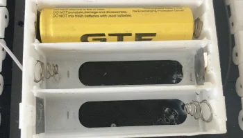
— 2 x 13650 or smaller Li-Ion batteries (I obtained mine from disposable vapes)
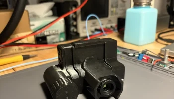
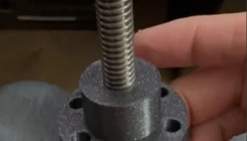
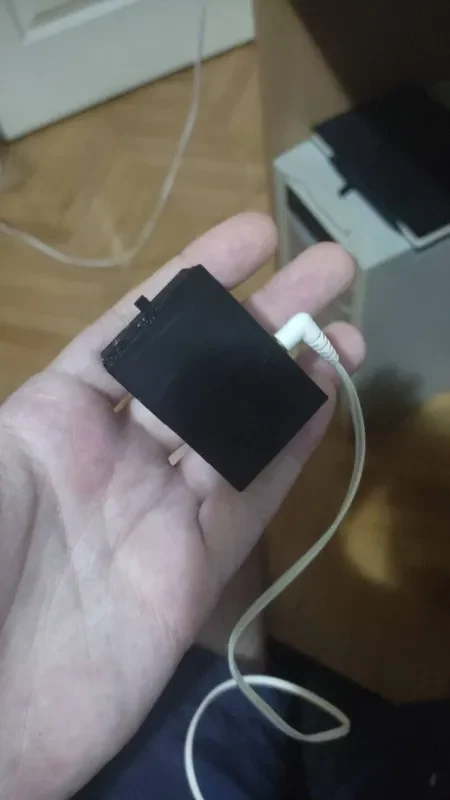
— A toggle switch (3mm thick stem), can be seen in photo 3.
— Optionally 2 x 5.1kOhm resistors in a very small package (I used 0805s) (For proper Type C power negotiation)
— Optionally 2 x (47 — 100) Ohm resistors for lowering the gain thus the noise floor (will be discussed below as to why)
— Optionally 1 x (100 — 200) Ohm resistor and a LED of your choosing (Power indicator when charging)
Assembly guide:
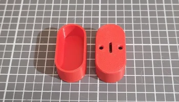
Print all of the parts. That's the stl files, not the scad.
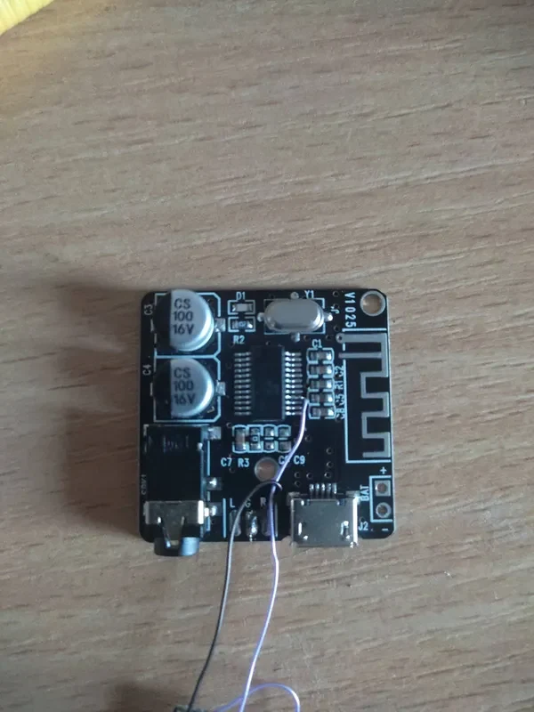
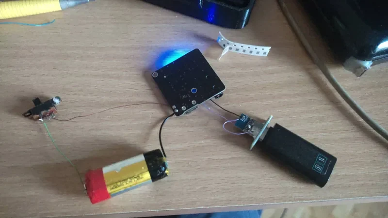
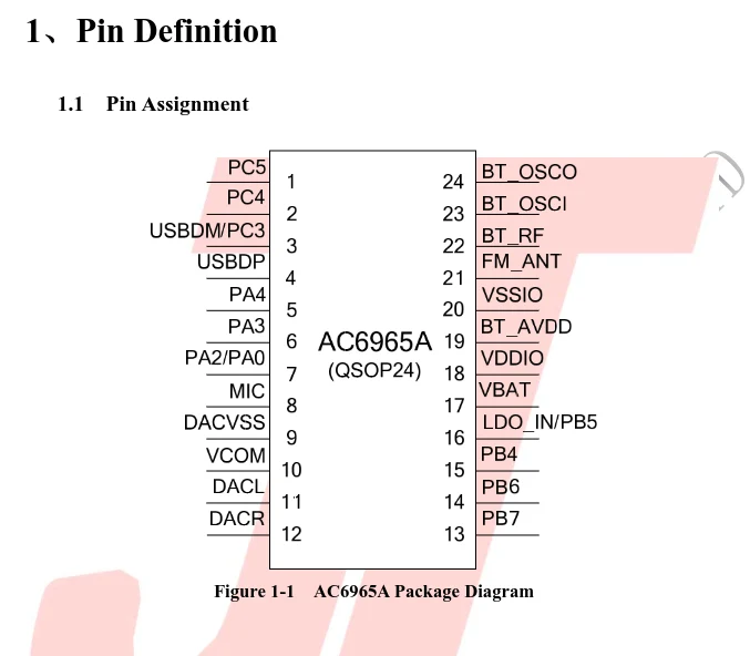
Solder a wire to pin 16 (LDO_IN/PB5) of the chip. Pin 1 is indicated by the circle on the actual chip package. Be careful NOT to short any other pins in the process. The result should look like the 2nd attached picture in this post.
That wire is your 5V charger input. Solder that to your USB C breakout's 5V pin. This will charge the battery properly.
NOTE: DO NOT USE THE BLUETOOTH BOARD'S INCLUDED USB C or MICRO PORT. THIS WILL SEND 5V STRAIGHT TO THE BATTERY AND CAUSE IT TO BLOW UP. Keep this in mind. This is why I hid the port in the design of the case.
Ground of the power input (USB C board) should be soldered to the ground of the Bluetooth board. There's no analog ground separation on this board (yes, this is horrible news for audio quality) so you don't have to worry about that.
2x 13650 is soldered in parallel to the provided pins on the Bluetooth board (they're marked on the silkscreen)
Before assembly, read ahead to do the required modifications in case you want to have them.
Assemble everything while taking care not to pinch the batteries' wires as you'll cause a short. On the top case that's holding the board there's a small guiding hole that I made for the batteries wires to go through.
As I haven't taken too much care to design the case (I'll leave that up to you people, I'm more of a electronics nerd) the parts don't really fit together and will have to be glued shut. I used hot glue.
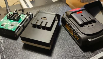
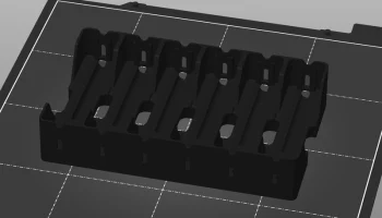
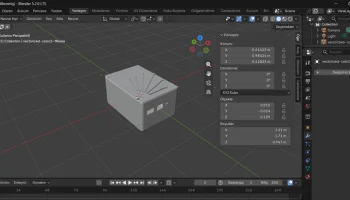
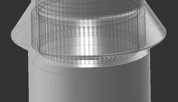
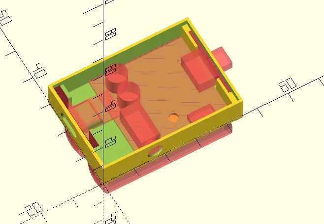
Here's how the parts should fit together (as shown in my CAD program),
The top contains: the bluetooth board, the USB board, the switch, while under it the bottom case houses the batteries themselves. The battery wires are guided through a hole which exists on the bluetooth board and the top case.
Other optional modifications that I had made:
1. Lowering the output gain.
This one is quite difficult to do and I'll recommend skipping if you're not comfortable with precision micro-soldering.
If you're using low impedance headphones like I do (20 to 30 Ohm), you'll probably want to reduce the power of the boards 3.5mm output. If you don't do this, you'll hear audible noise when the board is outputting an audio signal. This is not what you want. Shouldn't be a problem on high impedance headphones but I hadn't tested that.
In order to perform the fix:
You'll have to cut the each of the output channels traces AFTER the negative leg of their DC-decoupling capacitors which leads to the 3.5mm jack. This proved to be quite challenging as the trace runs UNDER those said capacitors so you'll temporarily have to remove them.
And in place of the cut solder a 100 Ohm resistor to each end of the cut and do it for both channels. That should roughly weaken the output by 10 times thus reducing the noise floor. It works as a simple voltage divider so that the power output going to your earphones is way smaller.
2. Having proper USB C power delivery charging.
Because my USB C breakout board is quite cheap and nasty you'll have to solder two 5.1kOhm resistors in order to properly trigger a «smart charger» and get it to charge your device.
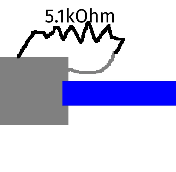
In order to mod the breakout board you'll have to lift a pin (very difficult but can be done reliably with some practice) and solder two 5.1kOhm resistors to each CC line.
The process is outlined visually because it's hard to describe through text.
Lift the pin
Once lifted, solder a 5.1kOhm resistor between it and the connector casing. Yes, this is quite difficult without steady hands.
Connect the other CC resistor
This should give you proper USB-C Power Delivery charging and thus the ability to use a smart charger.
3. An indicator diode to see whether the board is actually charging.
This one should be quite simple, just get a LED and a current limiting resistor (100-200 Ohms) and wire them as shown.
It will light up whenever there's power applied to the board so you'll know that its charging.
QnA:
How did I find about this?
I was researching to see if the chip featured on the board had any Li-Ion charging capabilities and it turns out I was right. Looking up your typical electonics datasheet websites for a Jie-Li AC6965A (which this board has) and returned the pinout where I found out that the chip is actually configured to work with a Li-Ion battery.
Excellent!
The board generates an audible humm when I use headphones?
See optional fix 1. Could be also related to the fact that this board has it's analog ground wired to the ground plane, and if that's causing the noise problem, then you can't really fix it.
Why can't I use the included USB port on the board?
Because it's directly wired to the battery line which would cause it to actually kill the battery and potentially you with it.
Why does my fast/quick/smart/reverse charger not work with this?
See optional fix 2.
I can't seem to turn off the device and charge it at the same time.
Yes, this is quite a annoying design issue. This board always stays on as long as its receiving power. In order to avoid this you should keep it turned on while making sure its not auto connecting to any Bluetooth device. But hey unlike earbuds, it lets you charge and use it at the same time :)
How long is the battery life?
With two 13650 cells being 600 mAh each, I roughly estimate about 20 hours of actual battery life, but that remains to be verified with a test.
I also included the OpenSCAD source if you're comfortable with it to modify the parts.
Drawbacks:
The board does not report or know the state of charge (ie. the battery percentage), once the battery is out the board will just die. Hopefully this is fixable in firmware as these things should be programmable.
The audio quality suffers from the fact that it does not have a separate ground plane for audio signals. This means that any Bluetooth/RF will leak into your audio signal path and create audible noise. This is practically unfixable without a whole board swap.
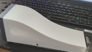
The thing is quite uncomfortable to hold due to the sharp edges I left in the model. But if someone with CAD skills is ready to clean this up, I'll be glad to properly credit them.