LoRa SolarNode v2.0 - solar Meshtastic / MeshCore repeat...
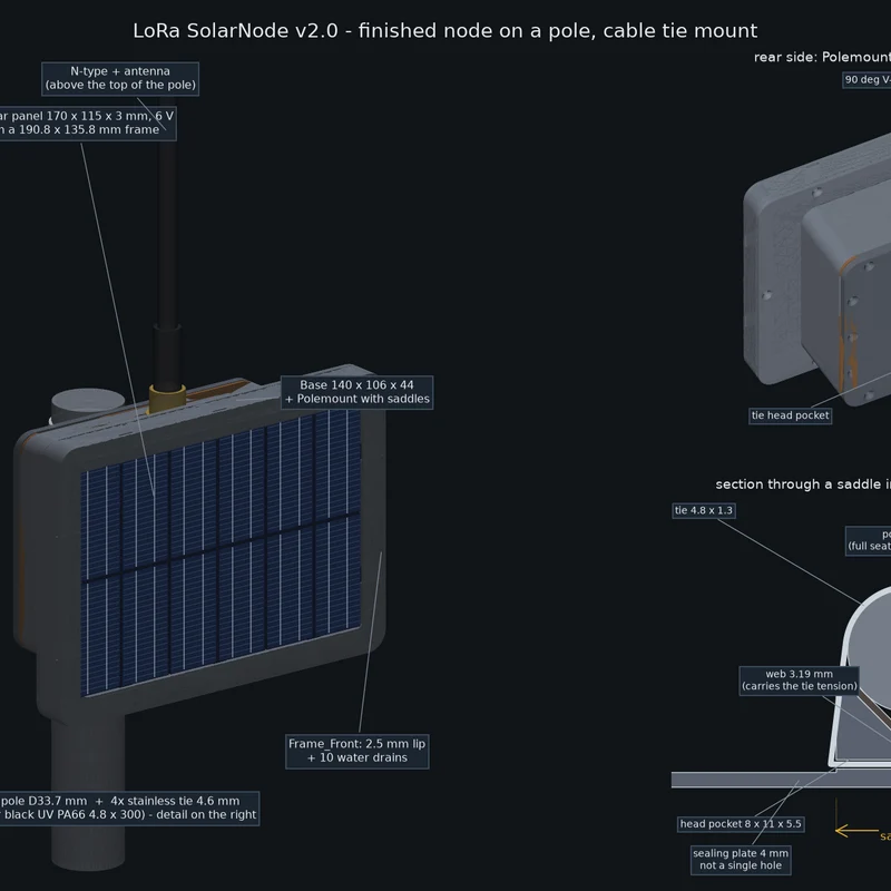
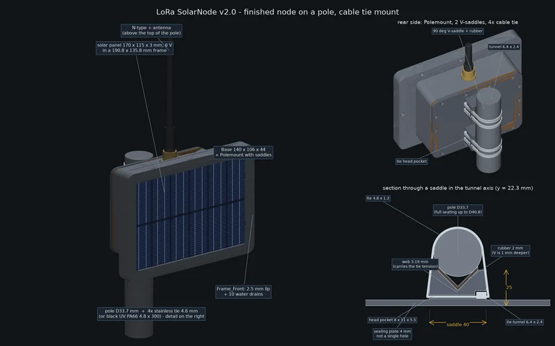
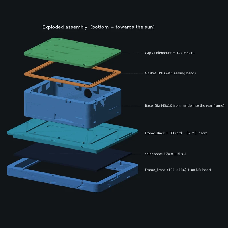
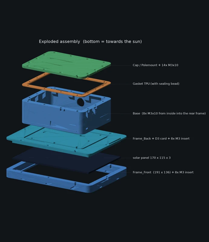
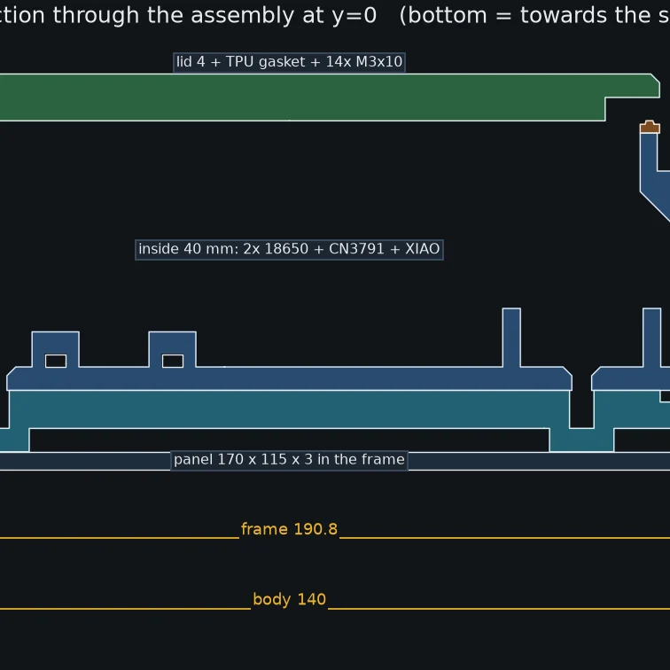

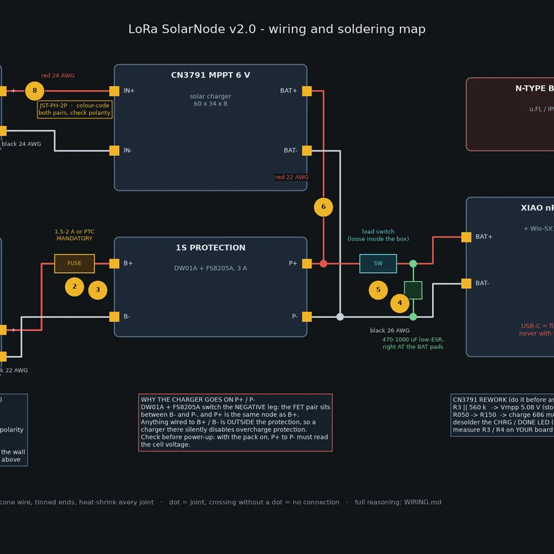
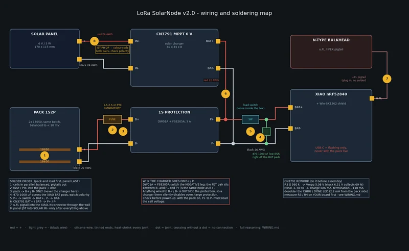
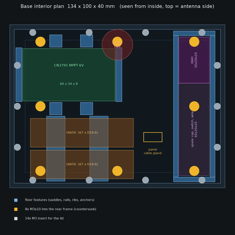
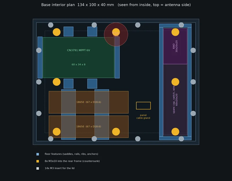
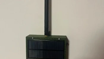
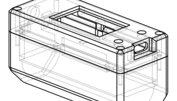
A parametric, printable, weather-resistant enclosure for a solar-powered Meshtastic /
MeshCore LoRa repeater node.
Designed around a 170 x 115 mm / 6 V / 3 W panel, 2x 18650 in parallel, a CN3791 MPPT
charger and a Seeed XIAO nRF52840 with a Wio-SX1262 radio — but the whole model is
generated by a Python script, so a different panel or a different board is one number and
one command away.
WHAT MAKES IT DIFFERENT
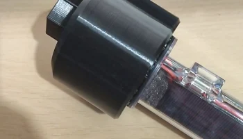
* The panel is clamped between a front and a rear frame, and the frame assembly bolts to
the electronics box with 8 screws driven FROM INSIDE. There is not a single screw head on
the outside of the enclosure, so there is no path for water to follow. Taking the panel
off is a normal service operation, not a destructive one — nothing is glued.
* Sealing is a D3 silicone foam cord squeezed in a 3.2 x 2.0 groove, 452 mm all the way
around, plus a printed TPU gasket under the lid.
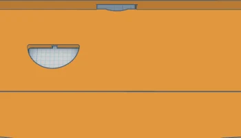
* The lip above the panel has 10 drain notches at panel surface level, so water and dirt
cannot sit in the tray it would otherwise form — in any mounting orientation.
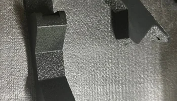
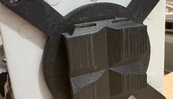
* POLE MOUNT WITH CABLE TIES. Two 90-degree V-saddles, each with two through tunnels for a
4.6-4.8 mm cable tie, plus a recessed pocket for the tie head. Four ties, no hose clamp.
Tension at 144 km/h works out to 33 % of two derated nylon ties per saddle, so the real
limit is UV and creep, not strength — use black UV PA66 or stainless ball-lock ties. The
tie tunnels are bridges ABOVE the sealing plate: the lid is never pierced.
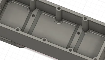
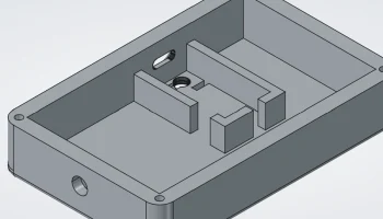
* Everything inside is held by cable ties, no screws into boards: two half-round 18650
saddles with four tie tunnels, a 90 mm channel with rails and end stops for the radio
board, and a seat with guide ribs and four tie anchors for the charger.
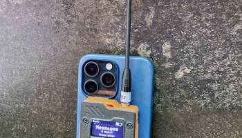
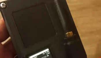
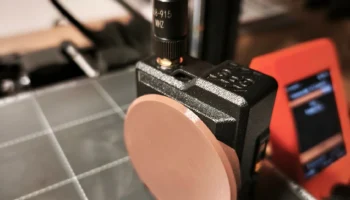
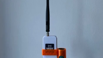
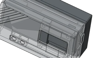
* A bulkhead N-type antenna connector with a teardrop hole (printable without supports)
and a cable gland for the panel leads that sits entirely inside the sealing cord.
* 110 automated checks run on the exported STLs: watertightness, assembly fit, insert
engagement, collision of every interior feature against every other one, bridge spans,
overhang area, and whether a D33.7 pole actually seats on the V walls with contact and
not collision.
WHAT YOU PRINT
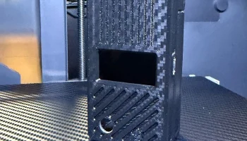
Frame_Front + Frame_Back + Base + Gasket (TPU) + Cap OR Polemount = five parts, no
supports, all exported already in print orientation. About 275 g of ASA plus 7 g of TPU.
WHAT YOU NEED BESIDES THE PRINT
30x M3 heat-set inserts, 22x M3x10 and 8x M3x8 countersunk stainless screws, 500 mm of D3
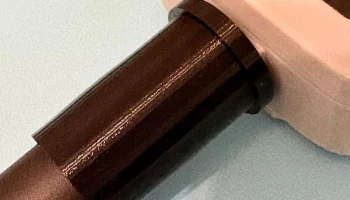
silicone foam cord, silicone sealant, 4+1 cable ties and a scrap of inner tube for the pole
mount. Full BOM, wiring diagram and a soldering order are in the linked repository.
ELECTRONICS, HONESTLY
The power chain is panel -> CN3791 MPPT -> 1S protection board -> XIAO BAT pad. There is no
5 V rail: an earlier revision routed the pack through a boost converter and a USB adapter,
and dropping that is 2.2-3.6x more efficient and keeps the firmware's low-battery
protection working. The repository contains the full audit, including the one resistor you
should change on the CN3791 (stock it collects 69 % of what a 6 V panel offers, and 0 % of
a 5 V one), which pads on the protection board are outside the protection, and the
firmware defines that otherwise let the node shut down and never wake up.
MEASURE YOUR PANEL FIRST
The panel cavity is only PANEL_W + 0.8 mm and the thickness value in the model is
provisional. Measure the whole slab in the middle and at four corners before printing the
frame, and check Voc in full sun to find out whether you really have a 6 V panel — the
labels on this class of panel are frequently the number after a hidden regulator.